Making a Roadside Honey Stand with Stripe and an ESP32
A family member has started beekeeping recently and as a result has a surprising amount of excess honey. For a while now we've been trying to get him to set up a stand at a local farmer's market to at re-coup at least some of the cost he's sunk into his new hobby. He hasn't been able to commit the time. So, I thought it would be fun to take a crack at building a kind of "honey vending machine" for him. How hard could it be?
As luck would have it, just as I was coming up with a plan for how to pull this off, a friend of mine posted on Instagram that she was trying to get rid of this old school spice cabinet.
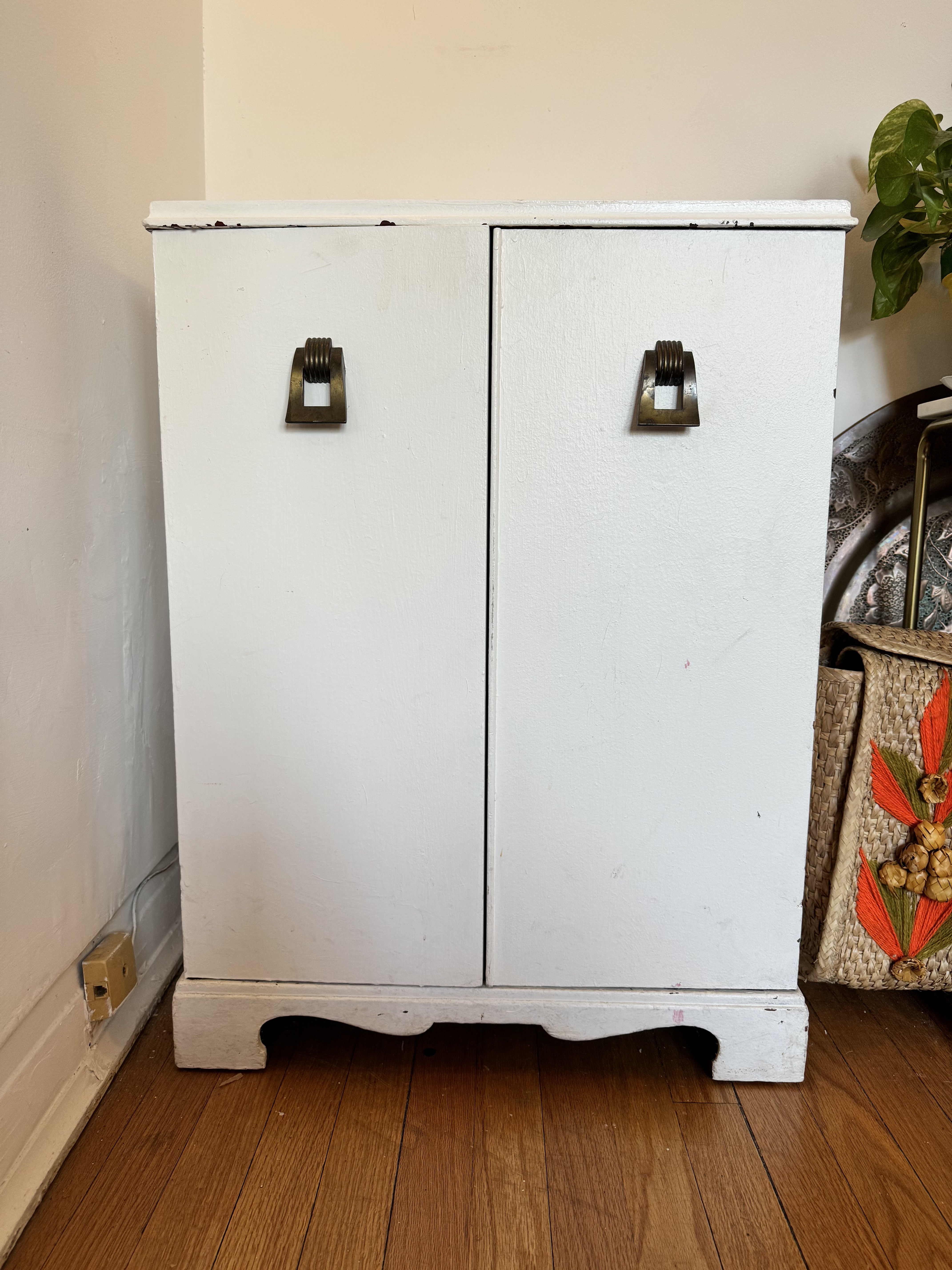
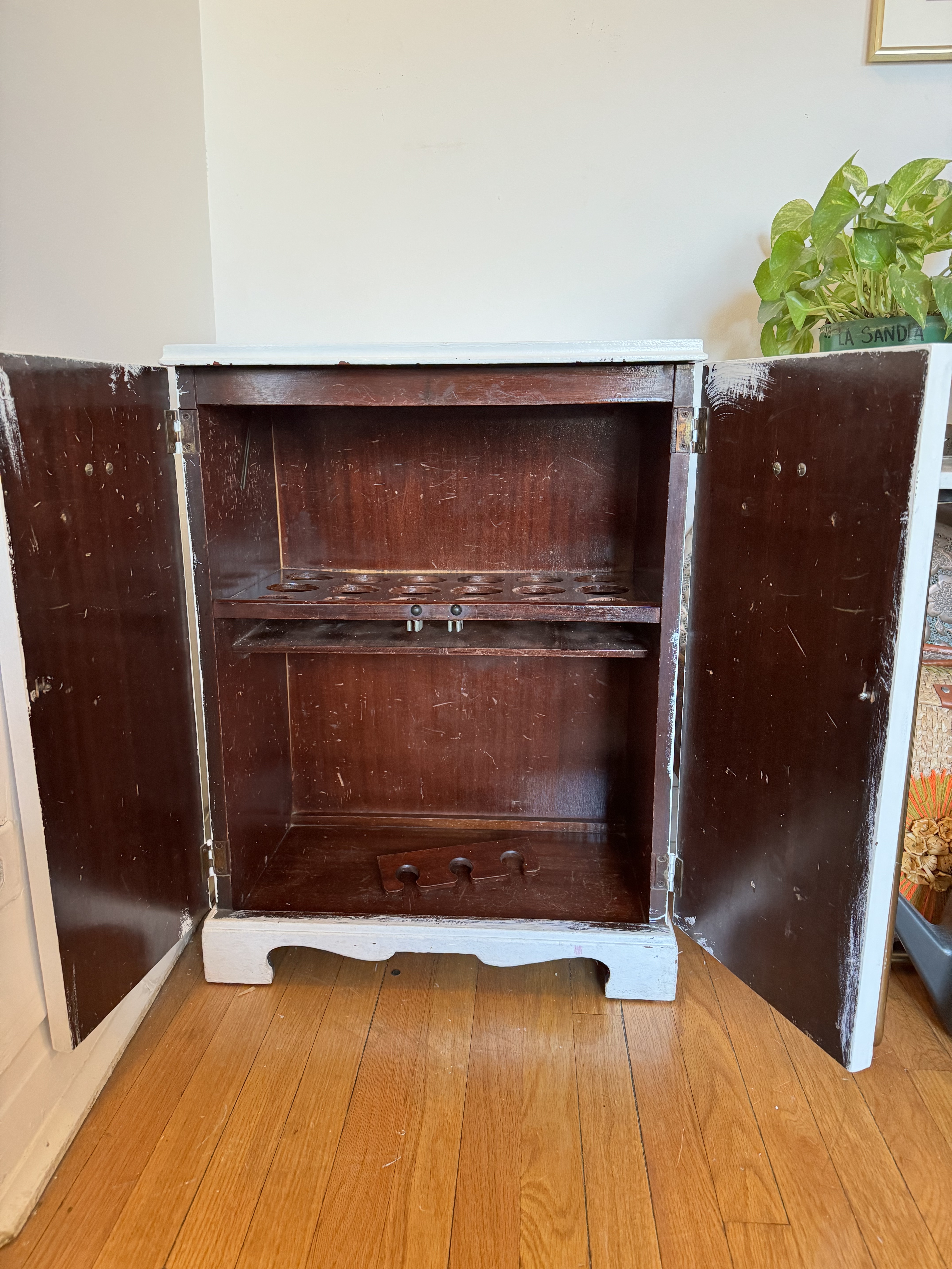
It has 12 cutouts sized for standard mason jars and 6 more for smaller spice jars. This would work perfect with these 4oz jars for the honey. I first started to think about the locking mechanism. In my mind, the biggest problems with unattended roadside stands (for firewood or produce) is the unattended cash box and relying on the honor system. This might be fine 99% of the time, but what's the fun in that?
I planned on using Stripe payment links. I get payment UI and hosting out of the box. I even get neat QR codes. I could spin up a lambda function to act as the webhook listener, waiting for the "checkout complete" event. Then trigger an MQTT message to my controller indicating to unlock the door. But, how to lock/unlock the door? I thought about using some of the servos I have laying around to actuate some sort of latch. After some digging I came across this solenoid actuated lock on Amazon. It seems perfect for this use case.
By the way, this service is now rolled into Thingio!
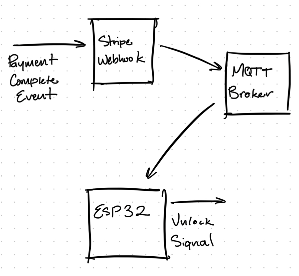
I would need some additional hardware since it needs 12V @ 2A to actuate the solenoid. I tried to make do with as many off the shelf modules as possible as I didn't really feel like designing the electronics myself. I picked up these MOSFET drive modules, a 12V DC power supply, and a step down converter (to supply 5V to my ESP32 module). Here's the basic connection diagram I came up with:

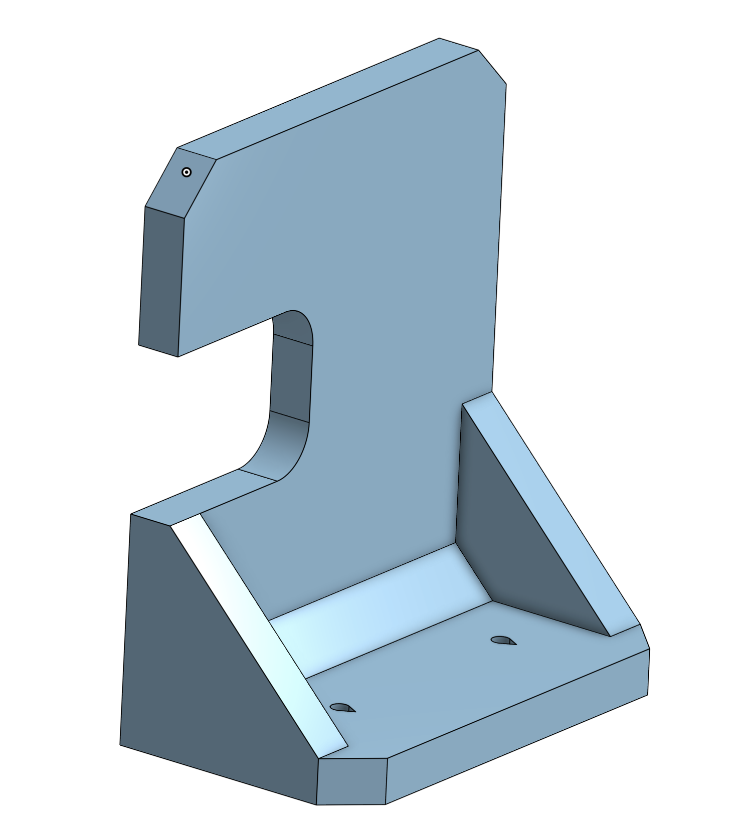
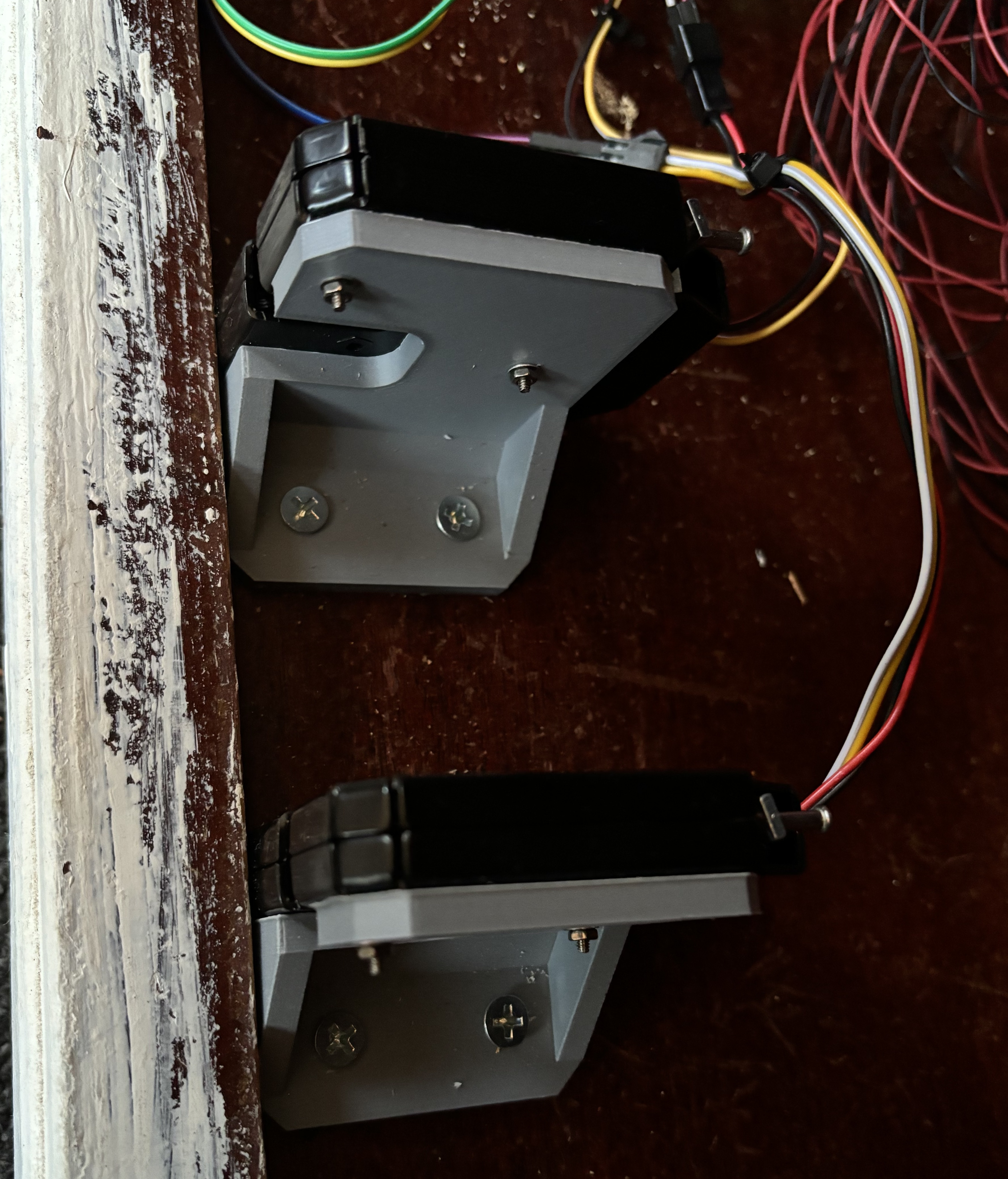
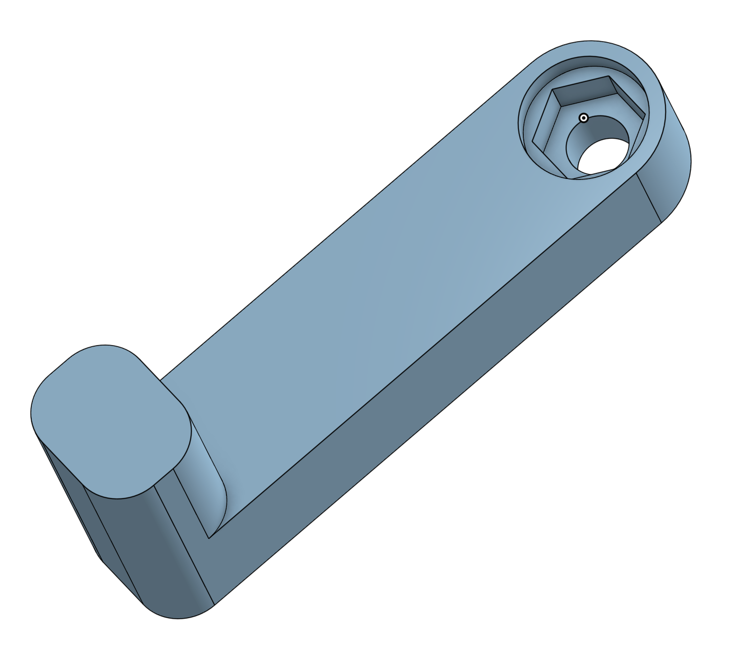
I also needed some way to mount the locks to the base of the cabinet. I took some measurements and ended up with this bracket (OnShape source) that I sent off to the 3D printer. I opted to drill the holes after the print was complete so I could make sure the hole layout that interfaces with the lock is just right.
Obviously, the cabinet has 2 independent doors so I had to double up on locking mechanisms. Thankfully the MOSFET module and step down converter modules come in packs of 5.
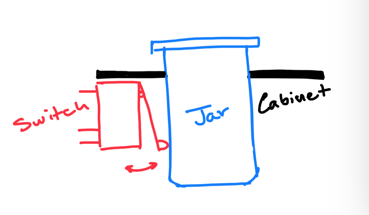
The next problem I ran into was how to handle a "sold out" scenario. We don't want a user to go through the payment flow only to have the cabinet open with no jars left. We'll need some way to count how many jars remain in the cabinet prevent any further sale if everything is sold out. I wrested with this for a bit. I went back and forth between light sensors, load cells, camera systems... and ended up landing on plain old limit switches. I found that if you mounted these switches right next to the cut out for the jar, they would make reliable contact with the jar when it was in place.
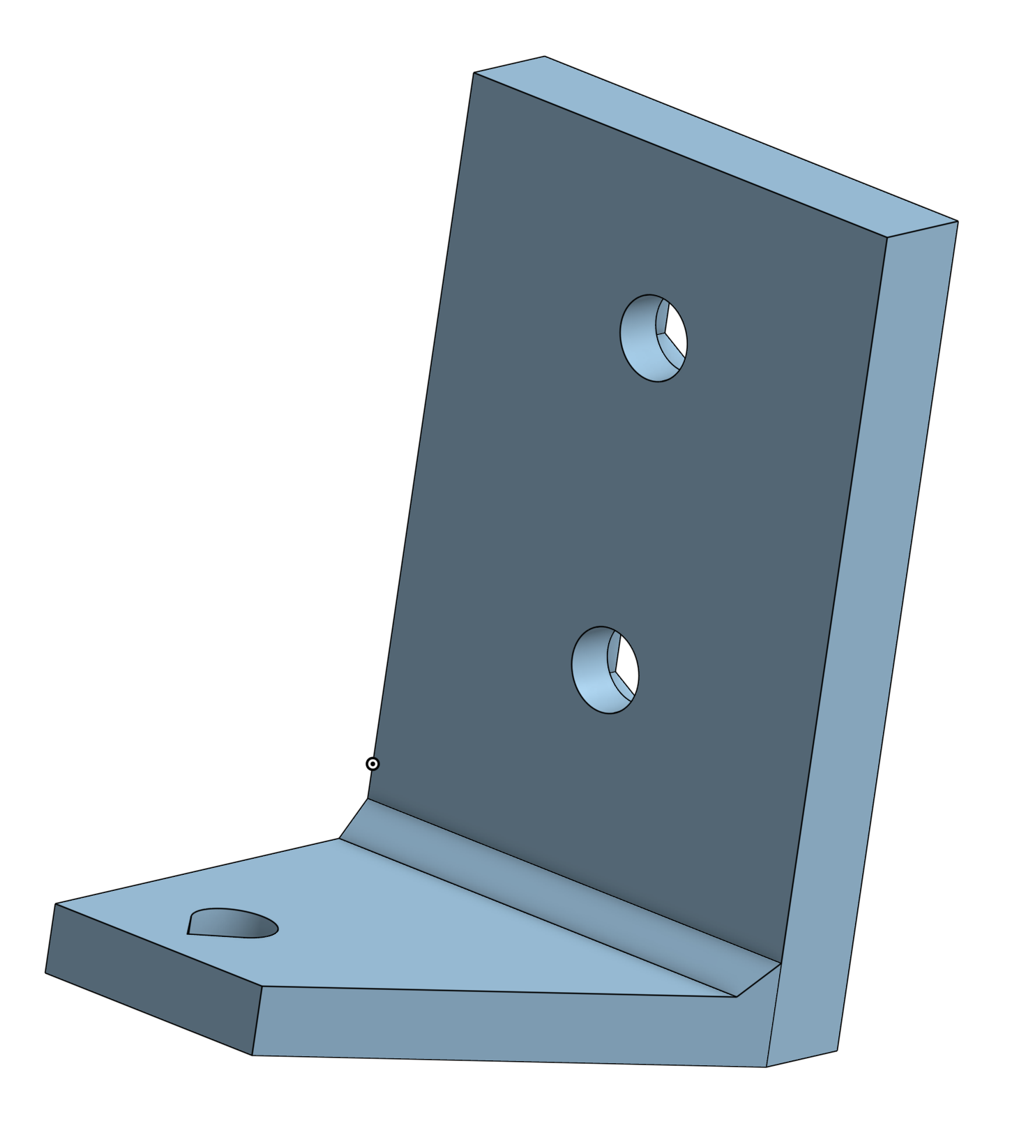
And here's what I ended up with for the switch's mounting bracket (OnShape source).
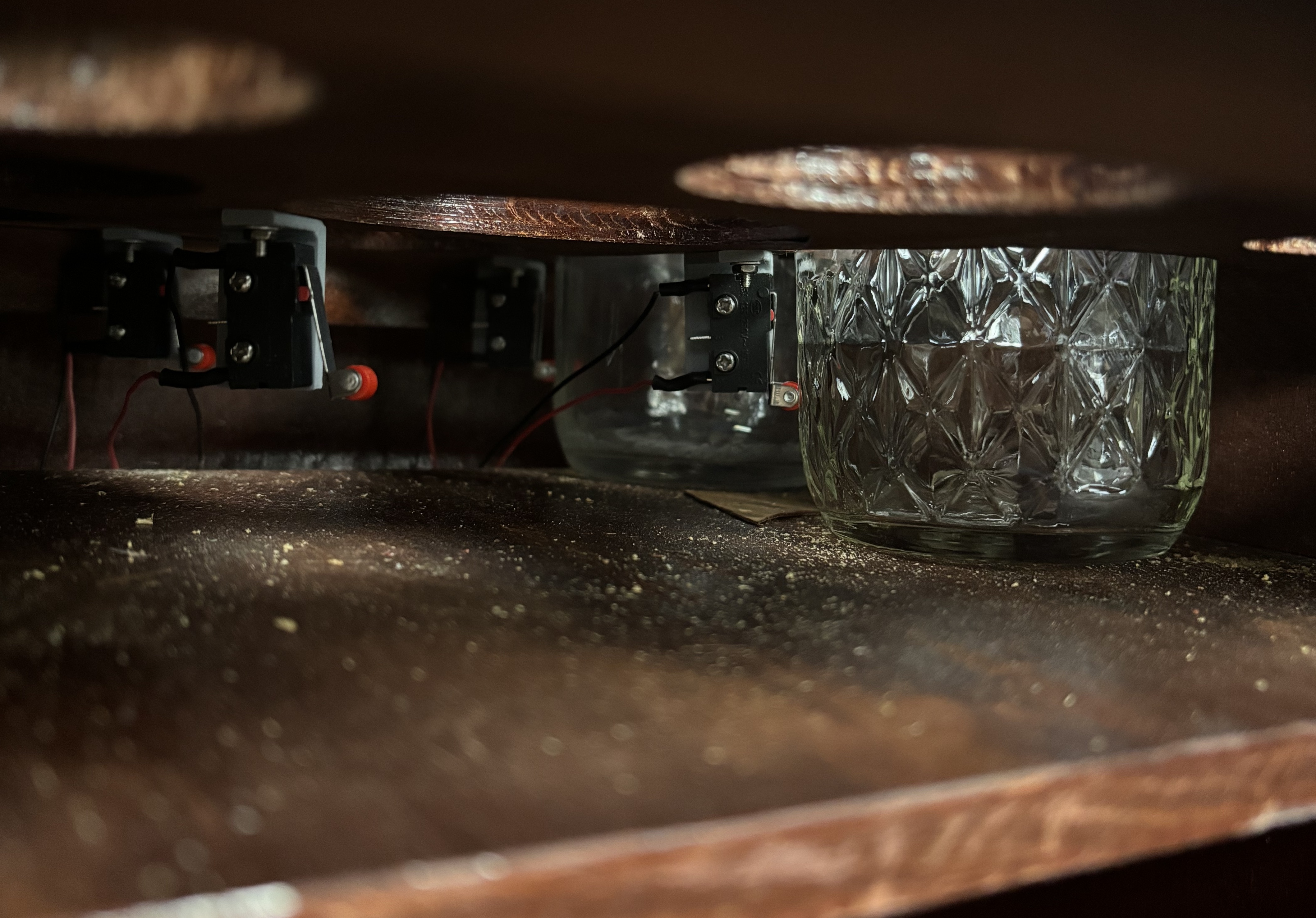
You can imagine from the picture above how hard it was to get my fingers underneath the switch assembly to hold the tiny M2 nut. I thought I was really clever with how I addressed it:
It's a 3D printed "wrench" that I can load up with a washer and nut and hold from above the jar panel. Much easier than going in blind from above and trying to thread on a washer and nut.
I would need 12 switches, one for each jar cutout. Way more GPIOs than my little ESP32 module could provide. Another off the shelf module to the rescue. It's a bit overkill since the CD74HC4067 chip can be used for analog readings, but it's easily available and cheap so I went for it. Plus, Adam Meyer put together a great guide on how to interface this chip so I didn't need to write a driver from scratch.
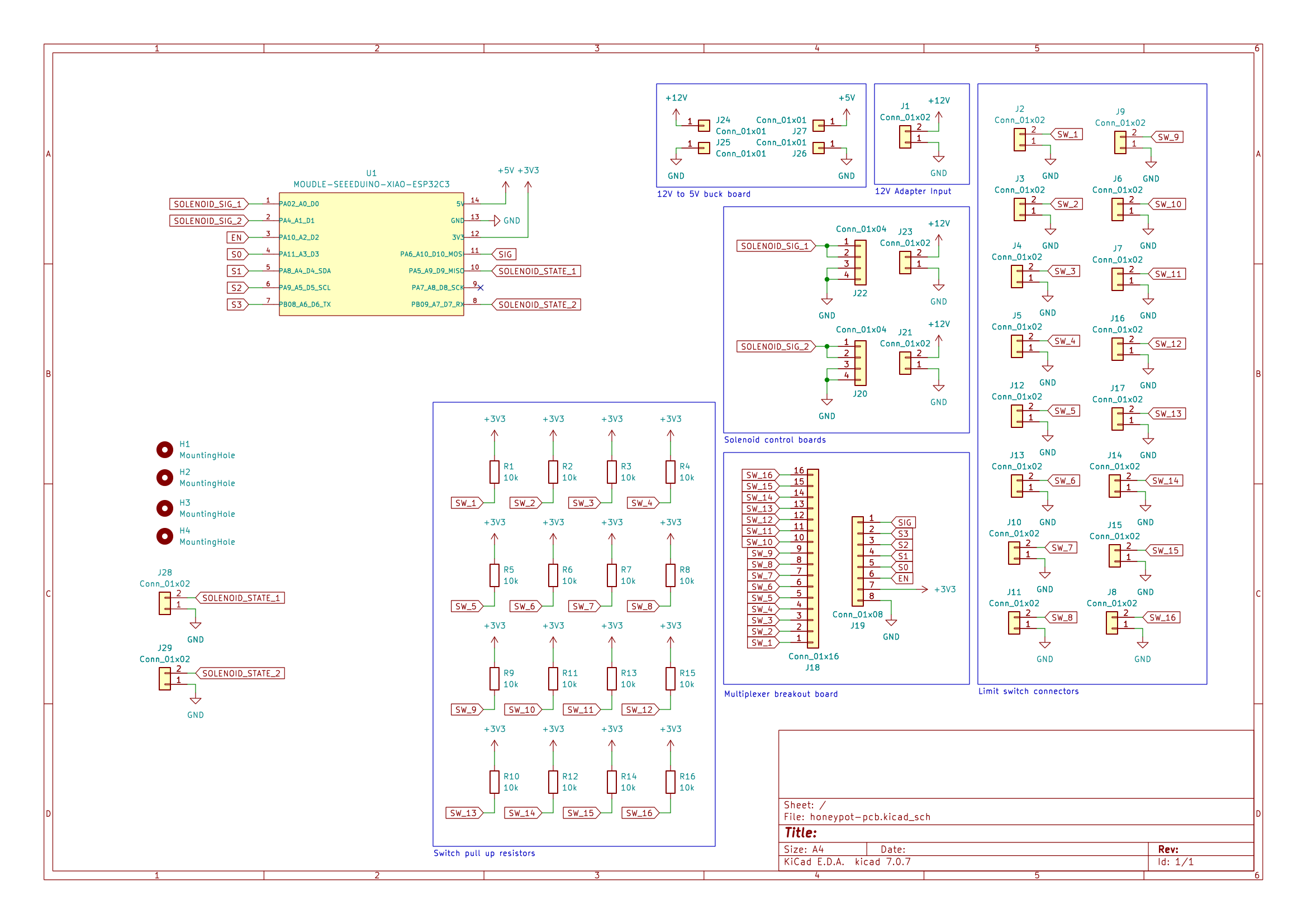
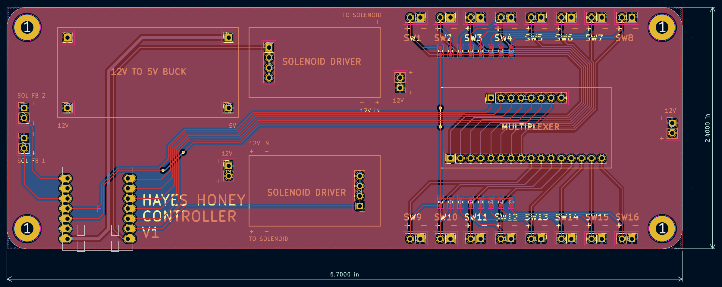
At this point this thing is going to be a mess of wires. To try and cut down on the chaos I decided to spin a PCB to connect all of the modules. Here's what I ended up with:
Here's the final BOM for the electronics:
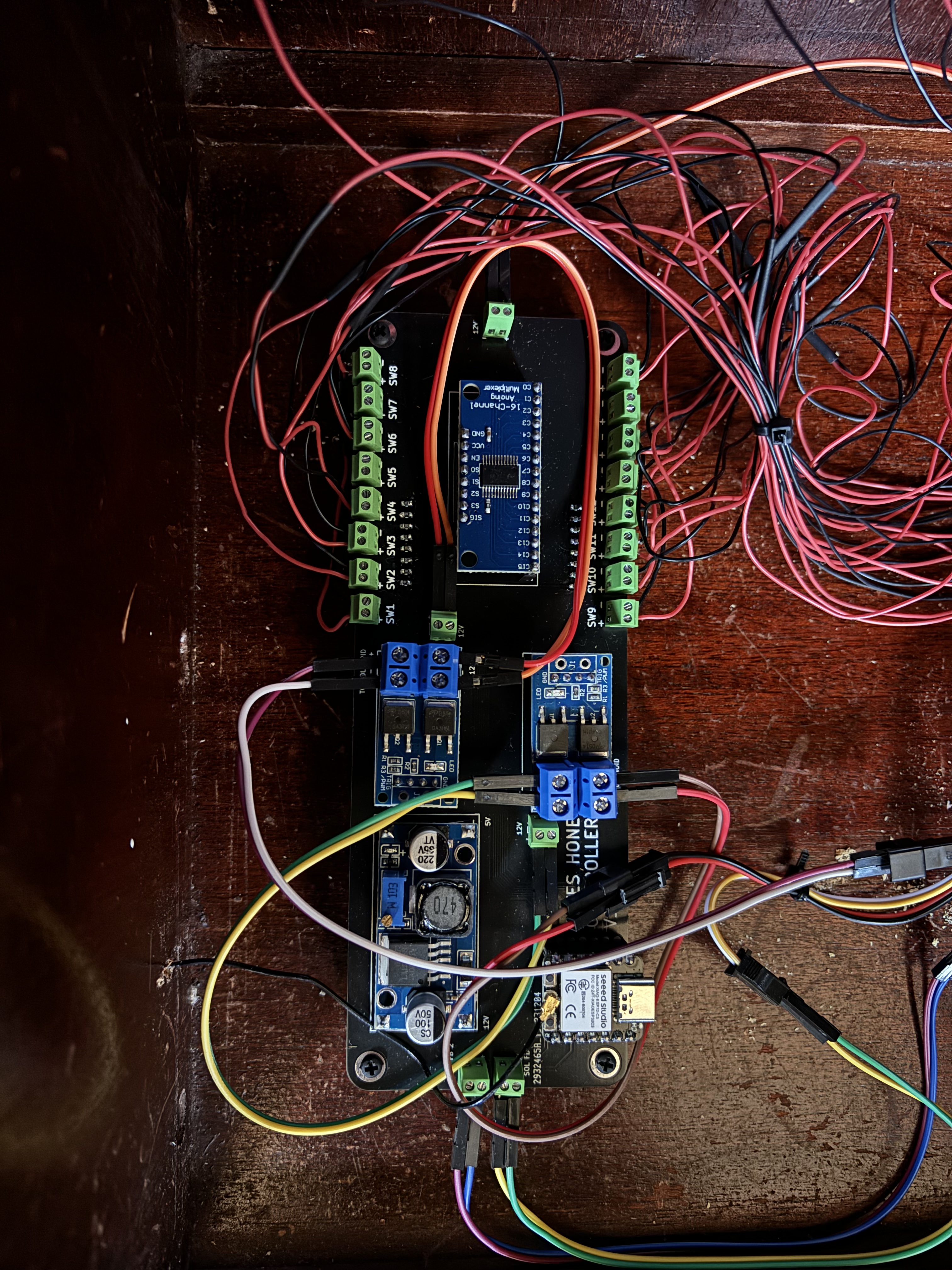
And the final PCB assembled with all of the modules (TODO: Cable management):
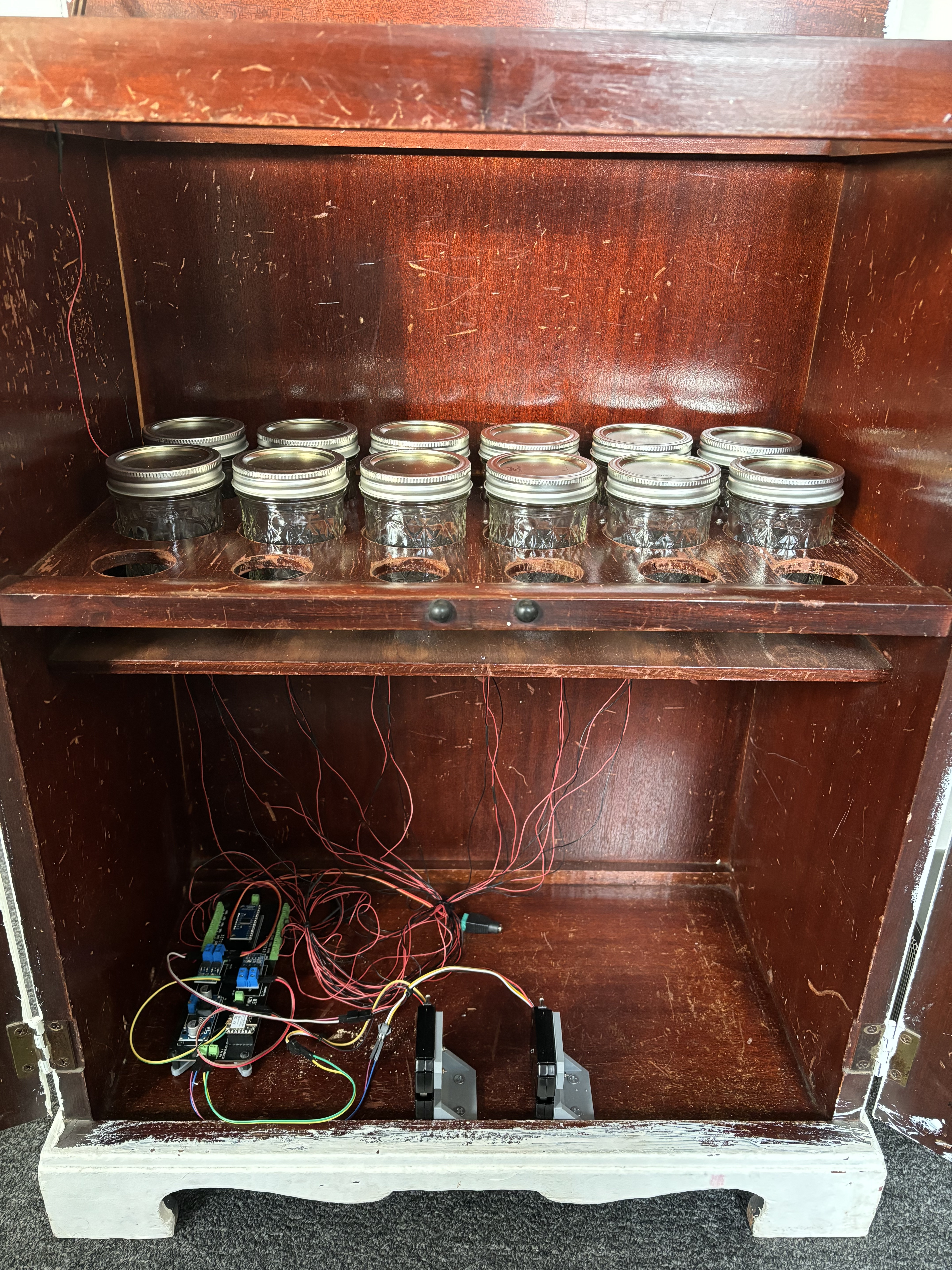
A demo of everything working!
After building this, the Stripe service is now rolled into Thingio. It abstracts a lot of this away for a one time deployment cost. Give it a try!